|
Back
to British Rail Home
|
McEwan, Pratt 10hp 0-4-0PM '677'
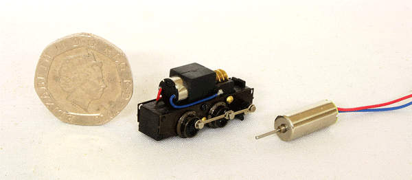
Completed Model with driver McEwan, Pratt built a number of small 0-4-0 petrol mechanical locomotives during WW1 years. Some were for use by the WDLR as 18in. and 2ft. gauges. Some standard gauge were also built. Somewhat resembling a steam engine without the chimney, these locomotives make an interesting prototype. I have been collecting information to enable me to build a 2ft. gauge version of this locomotive and have turned up some drawings of the 10hp version based on the former Abbey Light Railway locomotive. I have scaled them to actual size and it is very small! It will be a challenge, but I'm going to give it a go. Well, that was then and I hadn't started when Narrow Planet announced a kit using a new Japanese chassis with jackshaft. A kit was ordered (ref. NPL-016) along with a the chassis from Plaza Japan, this being a Tsugawa TU-DB 158. As supplied, the chassis has a 4.5v micro motor. I could have just added a resistor in series to run on 12v, but I had in the meantime already modified another chassis with the excellent Tramfabriek 12v micro motor. The kit's instructions actually recommend doing this. The new motor used is a Tramfabriek 0615S coreless motor and being 12v safeguards against accidental motor damage, but is a superior performer. The first thing to do was to re-motor the chassis. This is easily done by unsoldering the wires from the pickups and gently pulling the motor out. The worm gear has to be carefully removed and fitted to the new motor. In addition, a 3D printed chassis extension piece is provided and is fixed to the front of the chassis, i.e. the opposite end to the flycrank.
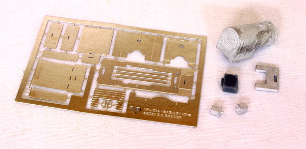
Chassis and replacement motor Various parts are supplied in the kit consisting of an etched nickel silver fret, cast white metal body and sandboxes plus a 3D printed chassis extension piece. Also included are various bits of brass wire and 'L' section for the valances. No couplings are included as these are down to modellers choice.
Parts supplied (excluding wire etc.) All these parts are very small and great care will be needed to assemble a good model. The white metal body section is a very clean casting and will need very little tidying up. A good read of the instructions help before anything is done. In addition, I had a look on NGRM Online to see if anyone else had already had a go. As it happens, someone has. It is always very useful to see how other people have tackled a build as there are usually more ways to build a model than just the instructions suggest. As I have fitted the Tramfabriek motor, I had to remove a small portion of the footplate to accommodate the longer motor. The instructions are very clear and an illustration provided. The starting point of the is the footplate, which having been removed from the fret, has the buffer beam bent down through 90 degrees. The next part is tricky. Two lengths of 0.5mm 'L' section brass are cut and soldered into the half etch on the underside of the footplate to represent the valances. Best to cut these slightly over length and file back. Now comes drilling the holes for the handrails, using a 0.3mm drill! This is best done slowly so as to not break the drill. The etched buffer beam with rivet detail is now attached to the footplate. There are slots on both the footplate and buffer beam for a Greenwich Coupling to be fitted. This is the suggested coupling and the slots will ensure the correct coupling height. I decided to deviate here slightly by fitting the coupling at this stage to assist with lining everything up. The next part is to add the cab sheeting. The longer inner rear sheeting is fitted first, the slots in which line up with the tabs on the footplate. The rear outer sheeting is then laminated onto the rear inner. I sweated the two sheets together, being careful to line everything up and not to unsolder the sheeting from the footplate at the same time! The rear buffer beam was then sweated onto the cab rear. This is where the Greenwich coupling is handy to line things up. The next part is also quite tricky. Two lengths of the 0.5mm 'L' section are cut to length and soldered to the half etches in the cab sheeting to form a return. The tiny tabs at the top of the sheeting are now folded 90 degrees to form the upper part of the handrail supports. I then deviated from the instructions and continued with the front cab sheeting. This also consists of an outer and inner section. The inner section has the two sides folded in at right angles. The tabs at the bottom of the sheeting should then fit in the slots on the footplate. The outer sheeting is in three parts, two sides and the front. These also have to be carefully sweated onto the inner sheeting, again making sure everything lines up. Particularly important are the holes on the front sheets. This is where the pin on the white metal bonnet inserts. Fitting the grab rails is next. 0.3mm wire is cut slightly overlength, with one end inserted into the holes in the footplate whilst the other end is soldered to the ends of the tabs. One of my grab rails was a bit skew and it seemed to be that the hole in the footplate wasn't quite in the right place. It was easily fixed by removing the handrail, re-drilling the hole and re-soldering. I then moved on to fitting the buffer beam irons. A jig on the etch is thoughtfully provided to get the curve and length right. These were then soldered into place along with the Greenwich couplings. The rear of the couplings had to filed back flush to allow the chassis to slide into place. Not much holding them on here, but should be more than adequate for the loads it's going to pull. This is a good point at which to test the fitting of the chassis. The next item I tackled was fitting the bonnet. A few minor tweaks had to be made to the casting before it was superglued in place. The sandboxes also needed a bit of fettling. I found that the bottom of the castings seemed a bit rounded and didn't sit flush to the footplate. Eventually I filed off the locating pins and squared up the bottoms before superglueing in place. There is another white metal casting for the cab floor to add and distribute more weight. This needed very little fettling and was superglued in place. The actual cab floor is an etch to which the handbrake column and wheel and the two gearbox levers are soldered to. I decided to make this up, test fit it, but leave final fixing until the model is painted. It would be very awkward to paint the cab inside with these in place.
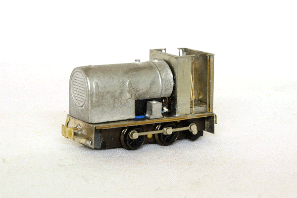
McEwan, Pratt assembled As can be seen from the above photograph, a minor amount of filling is required around the bonnet. You can also see part of the chassis, which will be painted black to make it less obvious. It must be pointed out that this is a tiny model and such close up photographs can be quite unkind! With this done, a quick spray of grey primer prepares the model for its final coat. The instructions suggest that these locomotives were delivered in an olive green, similar to Southern Railway Maunsell light olive, so I went with that.
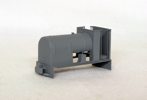
McEwan, Pratt primed and ready for painting In the event, Covid-19 struck and I was unable to get any paint for a long time. When I did, it ended up being Humbrol Khaki Matt Drab No.159. This looked about right to me and the body and parts of the chassis were painted this colour. The floorboards were painted with Humbrol Dark Earth Matt No.29. I was unable to find out what the gear levers and handbrake were painted, so I just opted for black. The whole model and parts of the chassis were then varnished with Testors Dullcote.
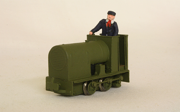
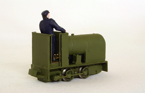
Completed model with driver Two other queries didn't manage to get answered with this model. Were the beams originally painted red? Contemporary photographs would suggest not, but the preserved one does had red beams. Is this a later addition. I decided, in keeping with my other WDLR locomotives to keep them green. The other query concerned the exhaust pipe and silencer. The kit doesn't supply one, but contemporary references made mention of the silencer 'glowing red hot' after sustained use. The preserved one does have a silencer fitted, just in ahead of the front axle in the above image. Is this a later fitment? If the originals had silencers, were they like this, or even in the same place? I decided to add a driver figure as the open cab looked peculiarly empty, but not in Army uniform. The figure is white metal, so adds a little useful weight to the rear.
Completed model from the rear I found the couplings had to be bent up slightly in order to couple up to my stock. The worm gear in the cab is visible from certain angles, like in the above image, but the driver obscures it a bit and is not really noticeable from normal viewing angles. Haulage wise, it does surprisingly well for such a small, light locomotive, hauling well in excess of what it did in reality. No doubt the replacement motor helps here. All in all, I'm very pleased with this addition to my narrow gauge fleet. A good little runner of an unusual and quirky prototype.
|
